Put here your reports, thanks!
Vsebina
PIFpockets and Other Experiments
Photos >> https://www.flickr.com/photos/plusea/albums/72157671778251606
PIFpockets wearable/mobile studio addition >> http://www.plusea.at/?p=5385
Analog Needle Stroke (with Cedric Honnet) >> http://www.kobakant.at/DIY/?p=6188
Tilt Sensor Demo >> http://www.kobakant.at/DIY/?p=6218
ohmGlove (using the One Chip Module VCO) >> http://www.kobakant.at/DIY/?p=6184
Conductive fabric microbial fuel cell (made during Interspecifics workshop) >> http://www.kobakant.at/DIY/?p=6186
5V breadboard powersupply
- no pcb just few parts by Bastl Instruments
http://www.instructables.com/id/5V-Breadboard-Powersupply/
one chip modules
by Bastl instruments
https://github.com/bastl-instruments/one-chip-modules
PIFcamp 2016 SoundLapse
https://soundcloud.com/kaziem/pifcamp-2016-soundlapse
Another in series of 'SoundLapse' recordings. A short audio sample is recorded every 3 minutes. The duration of each sample is chosen randomly between 20 and 200 milliseconds. Then the samples are put together into one audio file.
Can you hear the pattern? Can you hear the time passing? This is the time of our lives.
By Kacper Ziemianin: https://ctrlfreq.wordpress.com/
Microbial fuel cells

RGB heart beat
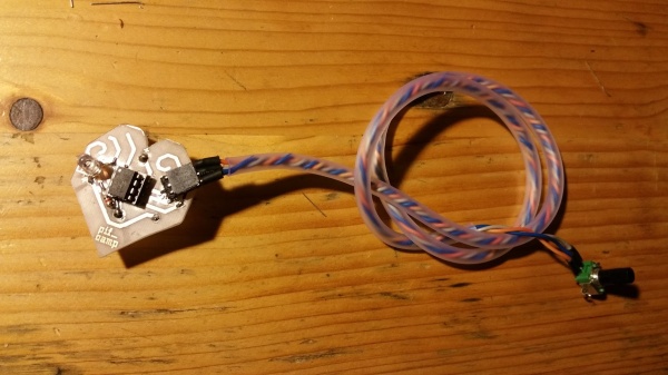
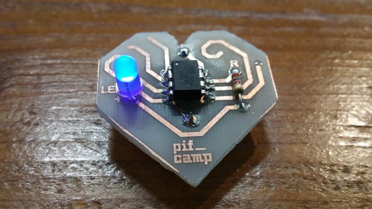
I upgraded the PIFcamp badge by choosing RGB LED instead of normal one. The LED is blinking in the rythm of a heartbeat, which is programed through ATtiny45. I added potentiometer with which i can control the speed of blinking and together with it changing the colours. When the rythm is slow, it blinks blue, which represent calmness; when it's at the normal speed, the LED blinks in green colour and when it blinks really fast, it turns red, it shows excitement. I couldn't realize the project without help from Cedric (PCB, soldering), John (programing, soldering) and Hannah (materials), so thank you all!
Materials: - PCB board - 3V battery - battery holder - 12 Ohm resistor - RGB LED - ATtiny 45 - ATtiny45 socket - Linear potentiometer - Reused wires - Soft transparent plastic tube - Shapelock thermoplast
Code:
int sensorPin = A1; // select the input pin for the potentiometer int ledPin = 13; // select the pin for the LED int PowerPin = 1; int BluePin = 3; int GreenPin = 4; int RedPin = 0;
int GreenValue = 0.30 * 1023; int BlueValue = 0.60 * 1023; int OffValue = 0.90 * 1023;
int sensorValue; // variable to store the value coming from the sensor
int delayTime;
int colourPin;
void setup() {
 // declare the ledPin as an OUTPUT:
 pinMode(ledPin, OUTPUT);
 pinMode(PowerPin, OUTPUT);
 digitalWrite(PowerPin,LOW);

 pinMode(BluePin, OUTPUT);
 pinMode(GreenPin, OUTPUT);
 pinMode(RedPin, OUTPUT);

 digitalWrite(BluePin, LOW);
 digitalWrite(GreenPin, LOW);
 digitalWrite(RedPin, LOW);
}
void loop() {
 // read the value from the sensor:
 sensorValue = analogRead(sensorPin);
 delayTime = (sensorValue / 2);
 if (delayTime < 92) {
   delayTime = 92;
 }

 if (sensorValue > OffValue) {
    // do nothing
 }
 else {
     if ((sensorValue>=0) && (sensorValue<=GreenValue)) {
        colourPin = RedPin;
     }
     if ((sensorValue>GreenValue) && (sensorValue<BlueValue)) {
        colourPin = GreenPin;
     }
     if (sensorValue>BlueValue) {
        colourPin = BluePin;
     }


     // turn the ledPin on
     digitalWrite(colourPin, HIGH);
     // stop the program for <delayTime> milliseconds:
     delay(delayTime);
     // turn the ledPin off:
     digitalWrite(colourPin, LOW);
     // stop the program for for <delayTime> milliseconds:
     delay(delayTime);

      // turn the ledPin on
     digitalWrite(colourPin, HIGH);
     // stop the program for <delayTime> milliseconds:
     delay(delayTime);
     // turn the ledPin off:
     digitalWrite(colourPin, LOW);
     // stop the program for for <delayTime> milliseconds:
     delay(delayTime);
 }
 delay(delayTime * 2);
}
By Manca Mencin
Hacking the camera triggering
The outcome of my bioluminescence based project at PIFcamp is a hacked remote switch (MC-DC2) for a dslr. At first it was ment as a part of the project for the purpose of triggering the camera with the light emited by the dinoflagellate's luminescence when perturbed. Camera would stand still on the tripod while the photos would be taken without pressing the button. After the algaes refused to emit light and I slowly started doubting in their vitality this became the main part of the project.
With the help of others I managed to make a photodiode based circuit on arduino which is connected to camera by cable. The photodiode that was used is sensitivive in the visible spectrum. Arduino is programmed in such way that the voltage produced by the diode is than multiplied by an factor (in code) and compared to the voltage on potentiometer which is used as a treshold for triggering. There is also a LED which turns on when the circuit triggers, so you can use it to calibrate the treshold in different circumstances without the camera being connected.
Pic: http://wiki.ljudmila.org/Slika:WP_20160730_23_00_31a_Pro.jpg
Video: https://drive.google.com/open?id=0B2jUDE3huRMIdGZ1bkxjQ195aG9CYVgtdndRbUxZcktQZE8w
Code used:
void setup() {
Serial.begin(115200);
} void loop() {
 // read the input on analog pin 0:
 int sensorValue = analogRead(A1);
 int referenceValue = analogRead(A2);
 int ledPin = 7;
 pinMode(A0,OUTPUT);
 digitalWrite(A0,LOW);
 pinMode(A3,INPUT);

 float sensorVoltage = sensorValue*50/1023.0;
 float referenceVoltage = referenceValue*5/1023.0;

 if (sensorVoltage > referenceVoltage)
{
 pinMode(A3,OUTPUT);
 digitalWrite(A3,LOW);
 digitalWrite(ledPin, HIGH);   // sets the LED on
} else {
digitalWrite(ledPin, LOW);
}
 Serial.print(sensorVoltage);
 Serial.print("\t");
 for (int i = 0; i < sensorVoltage*20; i++) {
   Serial.print("o");
 }
 Serial.println();
 delay(100);
}
By Jože Špehar
Collaborative PCB workshop
An instructable is now online: http://www.instructables.com/id/Collaborative-PCB-Intro
Title
Text...
http://link...


